Objective:
– To show how angular velocity (RPM) can be measured using a stroboscope.
– To show artifacts associated with the above.
Apparatus:
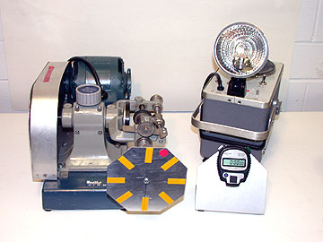
- Cenco rotator
- General Radio Strobotic Type 1531 stroboscope
- disk attachment (see Figure 1) mounted in the rotator
- stopwatch (optional)

Method:
A suggested angular velocity setting for the Cenco rotator is about 360 RPM. To achieve this velocity, set the driven wheel about 7mm from the center of the drive wheel. Place the stroboscope between about 0.5m and 1m from the octagonal disk.
Select the 110-690 RPM range on the stroboscope. Turn on the stroboscope and the rotator. Adjust the stroboscope until the spokes appear stationary. The red “dot” will also show as a single fixed image. A slight increase or decrease in the strobe setting will show an apparent slow rotation of the disk in the reverse or true direction of rotation.
Increasing the strobe frequency to multiples disk’s rate of rotation will yield images of fixed spokes and multiple fixed “dots.” One can also investigate the effect of setting the strobe frequency at half the rotational velocity.
Note:
The stroboscope calibration does not does not track exactly throughout the full range so expect some error in the measurement of multiple frequencies.
Optional:
One can use the stopwatch and revolution counter to determine the rotational velocity to confirm the strobe measurement. This manual method may also serve to emphasize the concept of rotational velocity or RPM.