Objective:
– To demonstrate how ground fault circuit interrupters work.
Apparatus:
- A/C power supply
- Digital voltmeter (multimeter)
- Small bulb mounted on board
- Two 400-winding inductors
- One 200-winding inductor
- U-shaped and I-shaped iron cores
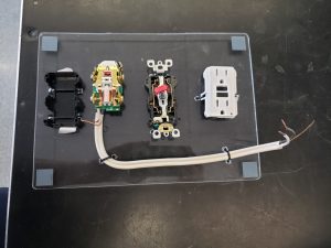
- Commercial GFCI spread apart on plexiglass board
Background:
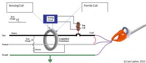
A ground fault circuit interrupter, or GFCI, is a sense-and-response system that is usually installed in outlets or breakers to protect people and equipment from ground faults. The GFCI monitors the amount of current flowing to and returning from equipment plugged into the power supply it serves. A ferrite coil encircles the hot and neutral wires (labeled as ferrite coil in the diagram). Each wire, the hot and the neutral, creates an alternating B-field circulating around the wires. These fields are amplified and conducted through the ferrite coil. A small sensing coil is wrapped around the ferrite coil and detects the magnetic field produced by the wires via the changing magnetic flux in this sense coil (Faraday’s law). If there is any imbalance larger than approximately 5 milliamperes, the magnetic fields no longer cancel. An alternating current is then created in the sensing coil circuit, activating the trip coil. Tripping the circuit cuts the current from the main power source so it is unable to reach the equipment. A GFCI can react as quickly as one-thirtieth of a second to prevent an electrical incident.

Figure 1. Schematic of GFCI circuit protector.
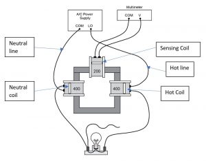
Here we model the hot and neutral slots of an outlet with the two coils fitted on the U-shaped iron core taking the place of the ferrite coil. The light bulb is our piece of equipment plugged into the AC power source. The top coil is the sensing coil which reacts to any A.C. magnetic flux, induced by an imbalance in the B-fields generated by any current difference going through the “hot” coil and the “neutral” coil. In the event of ground leak bleeding off some current, the induced EMF is recorded on the AC DVM.

Figure 2. Model of GFIC operation. Pay special attention to the way the currents enter the hot and the neutral coils. Why is this important?
Method:
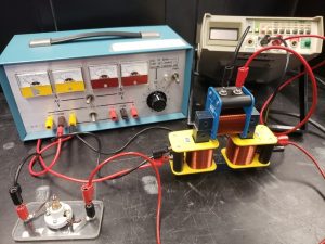
Connect the circuit as shown in Figure 2. Switch on the AC power supply. Note the AC voltage reading on the DMM (should be zero) and the state of bulb (it should be lit.). Touch the loose wire coming from the bulb to the COM of the power supply (while still on) to create inequality between current out and current in. Note voltage reading and state of bulb. If the voltage is not initially zero, you may need to flip the polarity of one of the 400 turn coils.

