Objective:
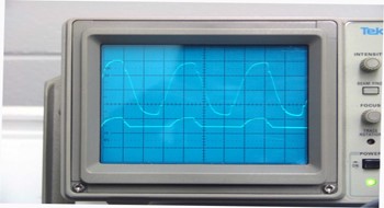
– To display the rectified AC waveforms for half wave rectification and full wave rectification with and without filtering.
Apparatus:
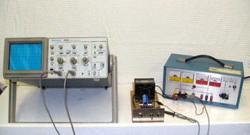
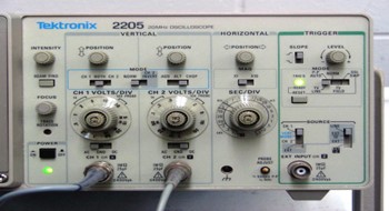
- Dual beam scope such as Tektronix 2205
- One 10X probe scope leads and one 1X set of scope leads
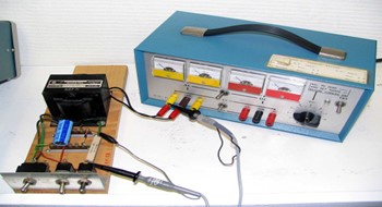
– Rectification assembly, consisting of:
- 12.6 V CT step-down transformer
- two silicon diodes
- switching to select half/full wave, filtered/unfilter
- SC4 AC power supply
 |
 |
 |
 |
Method:
Connect the circuit as shown in the picture. The following scope settings are recommended:
Channel 1 (connected to SC4 output to the rectifier board transformer)
- 20 volts/cm (10X probe)
- DC mode
Channel 2 (connected across the load)
- 2 volts/cm (1X leads)
Sweep speed = 5 ms/div
Turn on the scope and SC4 power supply. Set the SC4 to about 30 volts. Start with:
- 1/2 wave selected
- filtering off
- load IN (leave on)
Use the scope’s horizontal position controls to position the two waveforms for easy comparison.
Next use the switches on the rectification demonstrator to show:
- full wave waveform
- 1/2 wave and full wave filtered waveforms.
Note scope connections.
The 10X probe is connected to the higher voltage input side of the transformer and the 1X leads connected to the lower voltage load. Note that both the isolation transformer within the SC4 power supply and the step down transformer on the rectifier board prevent “ground loop” problems with respect to the scope connections.