Objective:
– To illustrate the behavior of inductors, capacitors and resistors in DC and AC networks.
To introduce the ideas of inductive and capacitive reactance and impedance.
Apparatus:
- power resistor
- 2 capacitors, non-polar (2 mfd, 600v), in parallel
- inductor (1.5 H)
- three knife switches, SPST
- power supply, general purpose (S4-C)
- lamp, 40 W, 30 cm high
- leads
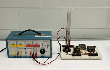
Method:
The R, L and C components are connected in series with a shorting switch across each component. The series-connected lamp serves as an indicator of current flow and magnitude, as well as providing a load for the network.
With the power set to DC the response to R, L and C is individually observed and inferred from the lamp brilliance. Then, with the power set to AC, similar observations are made. Concepts of inductive reactance, capacitive reactance and impedance are introduced and observed.
Note:
- Turn off the power supply and
- Set supply to “HI” range and
- Move the output leads to DC HI (& COM) or to AC HI (& COM) before turning on the power again.
- This setup works very well in displaying Lissajous patterns: Channel X = applied voltage Channel Y= Voltage across light (current sensing).