Objective:
– To show that the direction of induced current depends on the direction of a coil’s motion in a magnetic field.
– To show magnetic damping of a coil’s oscillations.
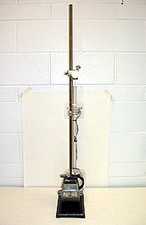
Apparatus:
- Coil and diode assembly
- Strong U magnet (as for DEM44)
- Stand with upper pivot.
Method:
SWITCH ON
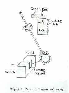
When the circuit switch is ON the coil output goes to the diodes with current flowing through whichever diode happens to be forward biased. For the geometry shown in the diagram, the red diode illuminates as the coil approaches the magnet from either side. This indicates clockwise current in the coil as viewed from the front. The green diode illuminates as the coil swings away from the magnet.
In this case current is counterclockwise.
For the induced voltages produced, the diodes only allow a small current to flow, hence damping is not evident.
SWITCH OFF
When the switch is OFF the coil output is shorted. The induced current will now be large enough to cause a strong damping effect on the coil’s oscillation.
Notes:
- The coil must be first aligned and then released carefully to avoid having the coil collide with the magnet.
- The diodes require at least 1.8 volts to emit significant light. To achieve sufficient voltage the coil must swing fairly rapidly past the poles of the magnet.
- The red diode “fires at a lower voltage and emits greater light intensity than the green diode. As a result, the red diode will display for lower amplitude oscillations than the green diode.