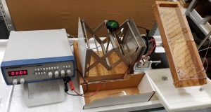
Objective:
– To model the movement of electrons through a conductor and the effect of temperature on the resistance of a conductor.
Electrons are modeled using steel balls, the conductor is modeled using a grid of nails, voltage is modeled by sloping the grid and temperature is modeled by causing the grid of nails to vibrate along an axis perpendicular to the slope.
Apparatus:
- Function Generator (BK Precision 4011A 5MHz)
- large speaker with mounting post attached to cone (as used in the
- vibrating wire demonstration)
- a pair of long spade/spade leads (connects amp to speaker)
- RCA/BNC lead (connects audio generator to the amp)
- lab stand and rod
- 90° clamp
- wooden support for speaker
- custom nail grid
- five 3/4″ steel balls, five 5/8″ steel balls and five 1/2″ steel balls
- stopwatch
Method:
Function generator settings:
- Frequency with Coarse and Fine Adjustment Knobs: 4~6 Hz
- Range: 50
- Mode buttons: none depressed
- Function: depress sine wave
- Duty Cycle, CMOS level, DC offset and .2dB: OFF
- Output level: about 2/3 of the whole range
Set up the apparatus and controls as shown above. The nail grid should be leveled along the axis of vibration, and have a 20° slope with respect to the horizontal.
Place all five 3/4″ steel balls into the top of the grid at the same time, and measure the time required for 3 balls to reach the bottom (median time for 5 balls to reach bottom).
Turn the power ON for the amplifier first and then the wave generator. Turn the volume control of the amplifier to 3. The grid should vibrate at 15Hz. Place all five 3/4″ balls into the top of the grid at the same time, and again measure the time required for 3 balls to reach the bottom.
It should take longer for the balls to pass through the grid when it is vibrating than when it is stationary.
Note:
Try various combinations of the slope, amplitude, ball size, material (steel or glass marble), frequency and observe the results.
