Modern engineering practice is to simulate circuits before building them. Simulation allows you to work more efficiently because you can build and test simulation models more quickly than actual circuits. Simulations allow you to quickly test your circuit under many conditions (different input signals, supply voltages, bias levels, temperature, component tolerances, etc).
Simulation is particularly important for integrated circuits because the NRE (non-recurring engineering) costs for an IC are very high and it can take several months to redesign a part to correct an error.
Simulations can’t duplicate every detail of the behavior of the physical circuit so whenever practical the design should be tested by building a prototype.
Many of the circuits you will build in the ELEX 3530 lab are simple enough and operate at low-enough frequencies that you can use a widely-used analog circuit simulator called SPICE (Simulation Program with Integrated Circuit Emphasis).
Linear Technology makes a version of SPICE called LTspice that you can download for free. This software includes models for many of Linear Technology’s ICs but it can also be used to simulate circuits that use other parts. Other IC manufacturers often make simulation models available for their components.
Instruction in analog circuit simulation and the use of LTspice is beyond the scope of this note. A tutorial presentation on LTspice should help you get started. For the circuits given below, you load the file, right-click to change parameter values if desired, run the simulation and then left-click on the schematic to select the node(s) to examine.
The files below contain LTspice models for some (actually, one) of the ELEX 3530 lab circuits. You can use these to simulate the circuits before you build them in the lab. Working through the lab with the simulated circuit eliminates some potential issues and can help you better understand the behavior of the circuit.
Differences between the simulated and measured signals can help you identify the cause of any problems. However, remember that differences may also be due to limitations of the simulator or the models rather than to a problem with your circuit.
The accuracy of the simulation results will depend on how accurately you specify the components. For example, the resonant frequency will vary from the simulated values due to component tolerances. Q’s will typically be lower than in the simulation because of losses in real components. You can measure the model parameters (up to 4 for capacitors and inductors) of the actual components you are using and enter them in your simulation if you want to get a better match to your measurements.
Lab 5 – Class C Amplifier
You can use small-signal analysis to find the resonant frequency of the output tank circuit.
However, you have to use transient analysis for Class C operation because the transistor is operating outside its linear operating range. In this case a simulation duration of a few milliseconds is required to make sure the circuit has reached steady-state.
Lab 6 – Quartz Crystal Characteristics
A crystal can be modeled as a capacitor. The series-resonant frequency is determined by the model’s series inductance and capacitance.
The manufacturer will also specify the maximum equivalent series resistance, parallel capacitance and parallel resistance. These values can be used to predict “worst-case” performance. However, since these are maximum values you cannot use them to predict the behavior of the specific component you will measure in the lab.
You can get specifications from manufacturer’s data sheets, for example CTS MP Series Quartz Crystal or ECS HC-49UX Quartz Crystal. Manufacturer’s web sites often have useful application notes such as this one on Quartz Crystal Design Parameters.
A simulation for Lab 6 could use a crystal (capacitor) model with values equal to half of the maximum specifications for series resistance (25Ω, 3.5pF and 250 MΩ) for the CTS 5 MHz crystal. The inductance and capacitance can be computed by assuming a Q (e.g. 100,000).
Lab 7 – LC and Crystal Oscillators
You can use a .step simulation directive to simulate the effect of changing the potentiometer to vary the amount of feedback:
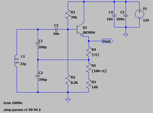
The schematic is available in Lab7a.zip.
Leave a Reply